There are two types of resistance measurements performed on parametric testers that require special considerations. The first is low resistance measurements. These are measurements in which the resistance of the device under test (DUT) is very small. The second is low voltage resistance measurements. These are resistance measurements in which the voltage drop across the DUT is very small. Problems compound when low resistance is measured at low voltages, which is sometimes required. Each of these tests has its own unique set of considerations, but each can be performed correctly if you follow proper procedures.
Low resistance measurements are difficult when the resistance of the DUT
becomes so small that the resistance of the tester itself becomes significant.
For instance, a Reedholm Instruments RI-40 parametric tester has an internal
resistance leading up to the DUT as large as 500 m![]() .
This does not include trace resistance, which can be 5 m
.
This does not include trace resistance, which can be 5 m![]() to 10 m
to 10 m![]() per inch. You can
ignore this low resistance when measuring high resistance, but not when measuring
very low resistance. At 5,000 ( a worst case resistance of 500 m
per inch. You can
ignore this low resistance when measuring high resistance, but not when measuring
very low resistance. At 5,000 ( a worst case resistance of 500 m![]() would cause only a 0.01% error. However, a measured resistance of 5
would cause only a 0.01% error. However, a measured resistance of 5 ![]() causes an unacceptable 10% error.
causes an unacceptable 10% error.
The easiest method of measuring resistance is the two-point measurement, either by forcing current (measuring voltage) or by forcing voltage (measuring current). However, this method introduces a significant measurement error because of resistance in the measurement path and the measurement equipment.
Two-Terminal Force Current - Measure Voltage Method
The first type of two-terminal measurement, the force current - measure voltage method is the more error prone of the two-terminal measurements. Figure 1 shows a typical configuration of this type of measurement. There are several resistances, both internal and external to the tester, that must be consider. The two resistances, rf and rs, are series resistances (relays, cabling, and other associated circuitry) between the power source and the DUT. The sense (S) leg resistance, rs, can be ignored because it is zero. The force (F) leg resistance, rf, can also be ignored because the voltage at point A is zero. The two resistances, rfg and rsg are series resistances of the force and sense legs to ground. They can be combined into one resistance, rg. The resistance, rh , is the series resistance between the tester and the high side of the DUT. The resistance, rl, is the series resistance between the tester and the low side of the DUT. These come from the trace resistances on the probe card, external cabling, etc. There is no built-in compensation for resistances rg, rh, and rl so they cannot be ignored. Rx is the resistance of the DUT. Therefore
| VTEST | = | ITEST [ rh + Rx + rl + rg ] |
| = | ITEST * Rx [ 1 + ( ( rh + rl + rg ) / Rx ) ] |
it can be seen that the measured resistance of the circuit is
| VTEST/ITEST | = | Rx [ 1 + ( ( rh + rl + rg ) / Rx ) ] |
which is Rx multiplied by a constant offset.
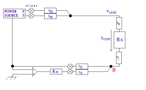
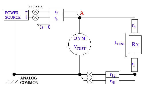
Two-Terminal Force Voltage - Measure Current Method
The second two-terminal resistance measurement method is the force voltage - measure current method. Figure 2 shows a typical configuration. This test method uses a driven ground in the digital voltmeter (DVM). The op-amp drives point B to zero volts. ITEST goes as high as necessary to allow this. Point B is essentially a ground point. Internal resistances of the meter, Rm, rfl (series resistance of the force leg to ground), and rsl (series resistance of the sense leg to ground) can be ignored since they are not in the ITEST current loop. The two resistances from the power source, rfh (series resistance between the power source force and the DUT) and rsh (series resistance between the power source sense and the DUT), can be ignored because there is error correction inherent in the force-sense scheme. This leaves only rh, rl, and Rx to be considered. The current in this circuit is
| ITEST | = | VTEST / (rh + Rx + rl ) |
This yields a total measured resistance of
| VTEST/ITEST | = | Rx + rh + rl |
| = | Rx [ 1 + ( ( rh + rl ) / Rx ) ] |
Note: The error term in this measurement is smaller than the error term for the force current - measure voltage method.
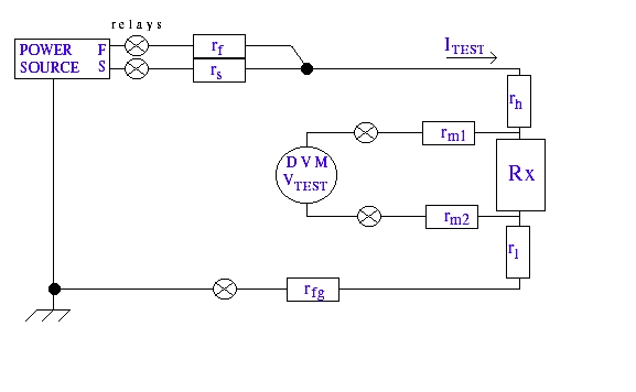
Four-Terminal Resistance Measurement
A more accurate method to measure low resistance is to use four-terminal measurements. Four-terminal measurements are done by forcing current and measuring voltage. Figure 3 shows a typical configuration for a four-terminal measurement. In this type of measurement, the power source is used to force a current through the DUT. A DVM measures the resulting voltage drop across the DUT. Resistances, rf (series resistance of the power source force to the DUT) and rs (series resistance of the power source sense to the DUT) can be ignored because of the error correction inherent to the force-sense scheme. Since the voltage is measured outside of rh and rl , these resistances can also be ignored. Additionally, the meter resistances, rm1 and rm2, can be ignored since no current flows into the meter. This results in
| VTEST | = | ITEST * Rx |
| VTEST/ITEST | = | Rx |
This type of measurement has no calculated error factor and is clearly the most accurate.
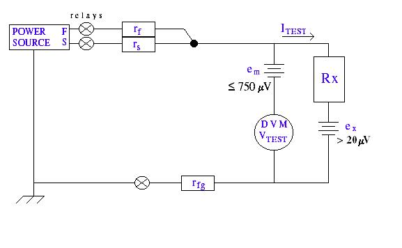
Low Voltage Resistance Measurements
Low voltage resistance measurements require special considerations. In these types of measurements, either the voltage forced on the DUT is low or a low current is forced through a small resistance resulting in a low voltage on the DUT. Thermal emf contributes to errors in this type of measurement. Thermal emf is a physical phenomenon in which a voltage is induced in a circuit by the thermocouple effect. The thermocouple effect is present wherever two dissimilar metals are joined. As the temperature changes, these two metals expand at different rates, causing the induced voltage. An example of this is where a lead-based solder joint joins a copper trace on a circuit board. There will be a small thermal emf voltage at this joint. Thermal emf voltages are small enough that they can usually be ignored, but when measuring very low voltages they can cause serious problems. Figure 4 shows a typical configuration for a two-terminal resistance measurement. There are two sources of thermal emf voltages in this circuit. The first, em, is a thermal emf voltage associated with the meter. This is an allowable system error that can be up to 750 �V. The second thermal emf voltage, ex, is associated with the DUT itself and is usually greater than 20 �V. In this circuit
| VTEST | = | -em + ( ITEST * Rx ) + ex |
| = | (ITEST * Rx ) + ex - em | |
| VTEST/ITEST | = | Rx ( 1 + ( (ex - em ) / (Rx * ITEST ) ) ) |
There are two methods that can be used to compensate for low voltage resistance measurement errors. The first is to simply measure the offset voltage caused by the thermal emf at ITEST = 0 and subtract this value from the measured resistance value. VTEST (at ITEST = 0) is equivalent to ex - em, or
| VTEST - VTEST (at ITEST = 0 ) | = | ( ITEST * Rx ) + ex - em - [ ex - em ] |
| = | ITEST * Rx | |
| Rx | = | ( VTEST - VTEST { at ITEST = 0 } ) / ITEST |
This method has limited accuracy due to the small signal size.
An alternative method is to use polarity reversal. The resistance of the DUT is measured using both positive and negative currents of the same magnitude. The offsets caused by thermal emf cancel each other in the following way:
| VTEST (at ITEST = -ITEST ) | = | ( -ITEST * Rx ) + ex - em |
| VTEST - VTEST ( at ITEST = -ITEST ) | = | ( ITEST * Rx ) + ex - em - [ ( ITEST * Rx ) + ex - em ] |
| = | 2 ( ITEST * Rx ) |
Therefore,
| Rx | = | ( ( VTEST - VTEST ( at ITEST = -ITEST ) ) / 2 (ITEST ) ) |
This type of measurement tends to be more accurate because of the larger signal size, but may not be usable in doped silicon or in test structures where protection diodes are present.
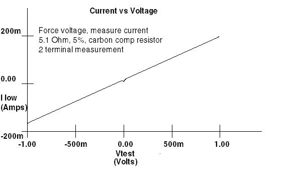
Illustrations of Resistance Measurement Errors
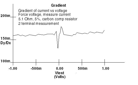
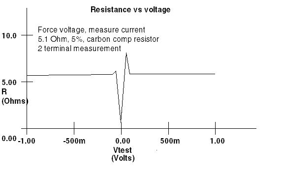
In order to graphically illustrate the resistance measurement errors, a Reedholm RI-40 was used to measure a 5.1 ![]() , 5%, carbon composition resistor. EMAGE was used to determine optimum test conditions. All EMAGE tests were two-terminal, force current - measure voltage tests. Figure 5 shows a current versus voltage sweep. This graph is somewhat deceiving because it appears linear. However, note that the curve has a slight dip as the voltage sweeps through zero volts. Figure 6 displays the gradient of (change in) current versus voltage and shows more accurately what is happening. As the voltage drop across the DUT gets smaller, the current becomes more difficult to measure due to the offsets caused by thermal emf. This is somewhat evident by the large changes in current near zero volts. Figure 7 shows the same effect on a resistance measurement. As the voltage drop across the DUT gets smaller, the resistance measurement becomes more inaccurate. Even when the resistance measurement is stable, it is off by a fairly large amount due to the large error factor associated with two-terminal measurements.
, 5%, carbon composition resistor. EMAGE was used to determine optimum test conditions. All EMAGE tests were two-terminal, force current - measure voltage tests. Figure 5 shows a current versus voltage sweep. This graph is somewhat deceiving because it appears linear. However, note that the curve has a slight dip as the voltage sweeps through zero volts. Figure 6 displays the gradient of (change in) current versus voltage and shows more accurately what is happening. As the voltage drop across the DUT gets smaller, the current becomes more difficult to measure due to the offsets caused by thermal emf. This is somewhat evident by the large changes in current near zero volts. Figure 7 shows the same effect on a resistance measurement. As the voltage drop across the DUT gets smaller, the resistance measurement becomes more inaccurate. Even when the resistance measurement is stable, it is off by a fairly large amount due to the large error factor associated with two-terminal measurements.
Summary
Determining the proper test methodology is very important to achieve the most accurate low resistance measurements. It is critical that you consider the physical limitations of the test equipment when choosing test conditions. Use the highest allowable current or voltage levels and use four-terminal measurements whenever possible. Ignoring the resistance of the test equipment or the effects of thermal emf can result in unacceptable errors in resistance measurements.